Preliminary Design and Thoughts on the Uniform Force Method – Strong Axis Connections
by Brian Craig Johnson, P.E.
Note: This discussion is for non-seismic (R=3) systems.
Engineers unfamiliar with the Uniform Force Method (UFM) in the AISC Steel Construction Manual may not know that the method has a fairly rigorous background and derivation that establishes the procedure as conservative. It is not an exact solution, but rather an equilibrium method that presumes a force distribution. The Structural Engineer of Record (SEOR) can use this force distribution concept to determine a preliminary connection geometry that is useful when developing conceptual details for design drawings. This approach estimates gusset size/geometry, and confirms the constructability of delegated connections. It also provides insight into how detailers/fabricators may estimate bracing connection geometry and collaborate with connection engineers to arrive at the final detailed connection.
In low-rise structures, workable gusset dimensions tend to drive the design more than forces.
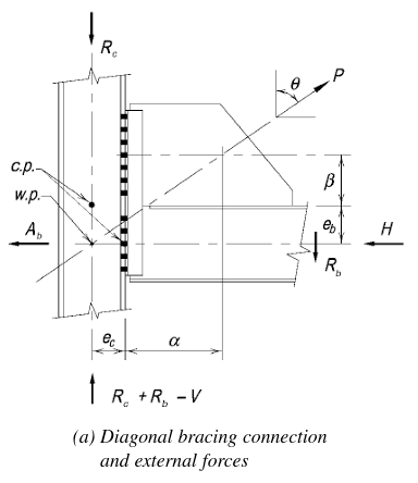
To use the UFM, equation 13-1 in the 14th edition steel construction manual must be reasonably satisfied.
![]()
Examination of the equation shows α and β are not “engineer-dependent” (if you would) commodities. θ, eb and ec are constants for each brace.
The equation is y – mx = b with different variables. There are thus infinite solutions.
Multiplying both sides by two produces a more direct equation, as the variables then become 2α (roughly the horizontal length of the gusset, which the estimator and fabricator both need early), 2β (the vertical length of the gusset), db (the depth of the beam), and dc (the depth of the column).
Note that the α and β values scale to the brace element’s horizontal and vertical dimensions. These dimensions set the preliminary gusset plate length and height.
For strong axis connections to columns, once θ is known, the engineer can select a “workable” dimension for β (2” to 4”, perhaps, considering the plate will be twice this dimension), and solve for α. Larry Muir’s NASCC seminar “Proper Application of the Uniform Force Method” discussed this process.
The above approach allows the SEOR to scale a gusset plate size based on β. This (at a minimum) leaves a force/stress check (and min. weld verification) to the connection design engineer. In flatter braces (i.e. large θ from bays longer than they are tall), small β values produce large α values. Here minimum welds (AISC Table J2.4) may work for stress since beam and column flanges tend to be thick, and gusset plates may need to resist buckling in compression. UFM welds are designed for some stress redistribution (Note: The weld ductility factor was reduced in the 13th and 14th editions to 1.25 from 1.4 in previous editions of the code). All these things make minimum welds more likely to govern unless the gusset is “small” compared to the forces it resists.
The gusset design may still change because the gusset to brace connection length and width must combat shear lag and net section/block shear. Check out AISC’s Design examples for some guidance.
These considerations allow the SEOR to develop preliminary bracing connection details, assess their efficiency, and give fabricators a plausible ‘baseline’ concept. The final connection is the responsibility of the delegated engineer. Detailers/fabricators can use this information as a starting point if they have not yet selected a connection design engineer. This allows them to influence the concept of the connection with their fabrication preferences, (i.e. field/shop welds, field/shop bolted, etc.). Estimating the connection geometry (particularly if they would prefer to change the final design) assists final connection details that are coordinated with the connection design engineer’s calculations and meets design, fabrication, and constructability intent.
Brian Craig Johnson, P.E., is a currently licensed or registered professional engineer (Civil) in 20 states. He is a licensed SE in Illinois.
The author gratefully acknowledges help from Larry Muir of the Steel Solutions Center for suggestions on an early draft of this article.