Are you familiar with the similarities and differences between the various seismic moment frame systems allowed by code? As the seismic hazard increases, more ductility is required, but how is that accomplished?
In the March 2023 SEU session, Matt Mester, PE, SE, from MiTek, Inc., presented Steel Moment Frames: Design Principles & AISC 341/358 Provisions. Matt identified the four types of moment frames allowed by the building code, and how to choose a system based on the seismic criteria. He then reviewed the design provisions contained in AISC 341 for SMF, IMF, and OMF systems. Matt also reviewed the AISC 358 connection types and why you would choose one for your project.
Depending on your seismic criteria, some moment frame systems are more appropriate than others. Matt noted that, when allowed, most engineers will select an R=3 moment frame system which is not specifically required to be detailed for seismic resistance. These R=3 systems are only permitted in Seismic Design Categories A, B, and C with no limits on height, and are typically found in a wind governed structure. AISC 360 dictates the design of these systems, and the LRFD or ASD load combinations for both wind and seismic must be checked, however drift limits typically control the design.
For areas of higher seismic activity, the design category may push the EOR to select a moment frame system that is specifically designed and detailed for seismic resistance. The three options include R=3.5 Ordinary Moment Frames, R=4.5 Intermediate Moment Frames, and R=8 Special Moment Frames. The three systems are required to have explicit deformation capabilities, strength requirements, and connection detailing limitations. Matt included these helpful slides in his presentation which are a useful quick reference for breaking down the differences in these moment frame systems:
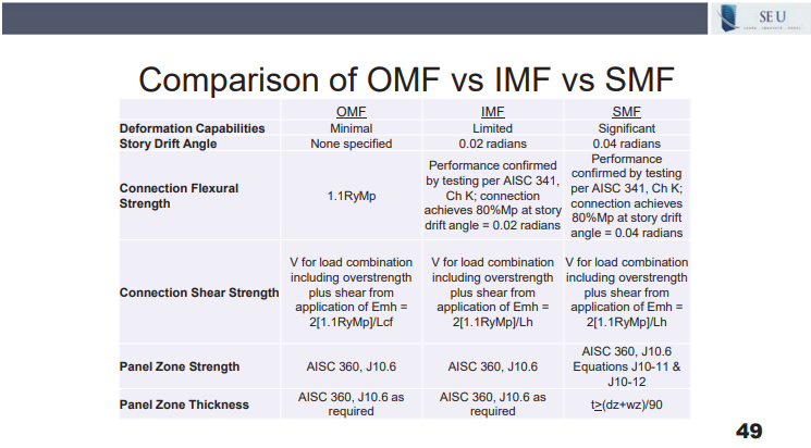
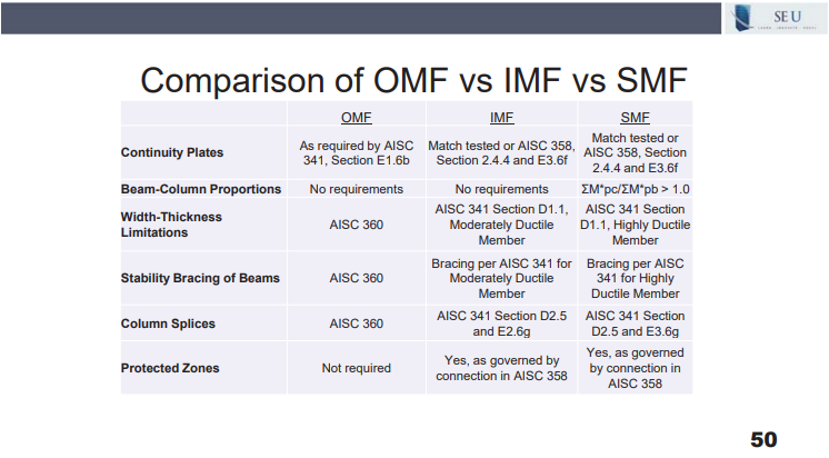
Using these chart comparisons, the EOR can identify the required drift angles, connection shear strength required, and various section references to find connection detailing requirements within the AISC 341 and 358. Matt noted that as the R value increases, the system ductility must increase, which leads to more stringent bracing and connection details which can be found in Chapter E of AISC 341. Being familiar with the differences between these systems can help engineers ensure compliance with the system ductility and drift requirements for their seismic moment frame projects.